The motherboard of my 3D printer was giving errors on the heat-sensors, but the sensors were OK. The malfunction had probably something to do with sparks when I recently plugged in the USB cable… So I ordered a Chinese replacement board (much cheaper than the original). However, when I installed this one, again there were lots of sparks near the USB port. Now this board was also giving multiple heat-sensor errors.
At first I thought the opamps connected to the heat-sensors were fried. Replacing a busted opamp did the trick for the original board, but the USB functionality on this board was also gone, so I decided to also repair the Chinese replacement board, which still had USB capability. I replaced the 2 busted opamps on this board. But after that, I still measured incorrect values on the output of the heat-sensors opamps.
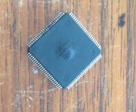
I started thinking: what if the CPU is blown (Atmega 2560)?
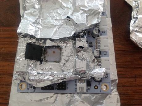
Ordered a replacement. Then I made an aluminum heat-shield, exposing only the chip. Put a small gas torch on it, heating it slowly. After 10 seconds or so, the solder on all the 100 (!) pins was liquid, the chip could move, and I could flip the chip. The brown spots in the picture are soldering flux. When I measured the output of the opamp pins with the microprocessor detached, the (3) values were all OK. Conclusion: the chip was indeed fried, and it distorted the voltages off the measurement circuit.
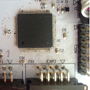
Now I removed excess solder on the PCB leads using a copper wick. Some pins are not used, and have no outgoing traces. When you heat these copper pads, the become detached from the PCB. This happened 3 times, but this is OK as the chip still has 97 leads to hang on the board 🙂
Using a small soldering iron, I soldered all 97 tiny leads. Then double checked for short-circuits.
After that, I needed to program the fuses of the Atmega 2560, and upload my custom firmware. I will not describe the process here, but surprisingly it worked on the first go.
W00t!

0 Comments