I am the proud owner of an umbrella-like design lamp. Unfortunately, it was hanging fairly low, and every now and then I would accidentally hit it with something. After a few years, 3 screws had broken off, and the screws were custom made…

Having postponed the repair job, I finally summed up the will to make new screws.

Hnnnnnn. There. Now or never!

First I drilled some 4 mm holes in a few pieces of brass. Then hard-soldered M4 thread onto them.

Putting the screws in a dremel and rotating it, I could make a perfect circle, that could be used as a template for sawing.

IMG_20160720_153136.resized

Then I put it back in the dremel, and using a file I shaped it into a slightly rounded form.

IMG_20160720_150833.resized

Next stop: creating a slot for the screwdriver, using a small metal saw.

IMG_20160720_151120.resized


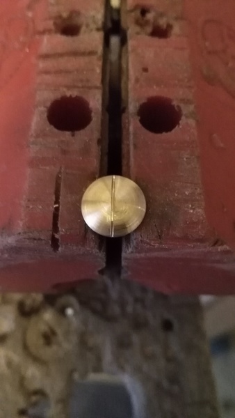
Rinse and repeat 2 x. The brass color is not really noticeable. See?

IMG_20160720_170151.resized

I also shortened the rod to reduce the height, thus reducing collision risks, but now the umbrella will not go up all the way any more. Not really an issue, though. Let’s hope none of the glass bulbs will break: I have not mastered the skill of blowing and sand-blasting glass .

IMG_20160724_153555.resized


The motherboard of my 3D printer was giving errors on the heat-sensors, but the sensors were OK. The malfunction had probably something to do with sparks when I recently plugged in the USB cable… So I ordered a Chinese replacement board (much cheaper than the original). However, when I installed this one, again there were lots of sparks near the USB port. Now this board was also giving multiple heat-sensor errors.

At first I thought the opamps connected to the heat-sensors were fried. Replacing a busted opamp did the trick for the original board, but the USB functionality on this board was also gone, so I decided to also repair the Chinese replacement board, which still had USB capability. I replaced the 2 busted opamps on this board. But after that, I still measured incorrect values on the output of the heat-sensors opamps.

I started thinking: what if the CPU is blown (Atmega 2560)?

Ordered a replacement. Then I made an aluminum heat-shield, exposing only the chip. Put a small gas torch on it, heating it slowly. After 10 seconds or so, the solder on all the 100 (!) pins was liquid, the chip could move, and I could flip the chip. The brown spots in the picture are soldering flux. When I measured the output of the opamp pins with the microprocessor detached, the (3) values were all OK. Conclusion: the chip was indeed fried, and it distorted the voltages off the measurement circuit.

heatmask


bubblechip

Now I removed excess solder on the PCB leads using a copper wick. Some pins are not used, and have no outgoing traces. When you heat these copper pads, the become detached from the PCB. This happened 3 times, but this is OK as the chip still has 97 leads to hang on the board 🙂

Using a small soldering iron, I soldered all 97 tiny leads. Then double checked for short-circuits.

resoldered

After that, I needed to program the fuses of the Atmega 2560, and upload my custom firmware. I will not describe the process here, but surprisingly it worked on the first go.

W00t!


Fat Dispersal-attempt nº 40 (FD-40) has started. The rowing machine used for this epic effort generates a bit of noise, which is probably transferred to the floor it stands on. Trying not to bother the downstairs neighbors too much, I came up with a cunning plan: air suspension.

Tennis-balls seemed like good candidates for the job!

IMG_20160410_154835[1]

A sport-shop salesperson had a opened can lying around, so for €10,= I am now the proud owner of 4 hairy, airtight rubber balls. They are contained by grey plumbing end-stops, but the fit is not what I would like it to be. So I printed some adapters.

More pictures later. Here is the model:

adapter


Currently, I am hacking my 3D printer’s printing nozzle, and need to know how hot some parts are getting. So I thought it would be fun/interesting to do some C-programming on a PIC, and read out a thermocouple to an LCD…

It works! The PIC is a farty old 8-bit DIP, but it works! 10 bits worth of A/D sampling, yay!

When the K-type thermocouple went glowing red in a lighter-flame, it stayed just below 400°C. What really surprised me is that it goes back to room temperature in mere seconds, and is not damaged by the heat. Supposedly they can get to 1370 degrees, but that seems a bit high?

b.t.w. the shown precision is fake, it’s just 48/1023 times * 500 ,  but who cares whether the nozzle temperature is 430.6 °C or 430.1 °C. Right?

IMG_20160403_225505

Waiting for the heat-switches to arrive, I found a plastic 130°C switch on an old battery, so I pushed forward with that one.

Rewinding the 12V coil was boring as expected, and because the wire already had bends from the initial winding, the result was not aesthetically pleasing. But a lot of insulating wrappings cover it up nicely, and it looks OK from afar.

And it delivers about 12 Volts!

Another item not yet ready for the scrapheap:

transformer_fixed.

Time to wrap this project up. The mickey mouse mirror is finished, and turned out really well. The left side is important, because  on that side cars are constantly overtaking me occasionally a Porsche is trying to keep up.  So it it nice to have 2 blind-spot mirrors on that side. To double check the fast cars.

On another note … perhaps you notice the blue cube in the first photo? It is a blinkenlight cam!

Cars have dashboard cams. Fnorkn also has a blinkenlight cam. To be discussed.

Thanks to a wise decision by the E.C. my lava lamp recently stopped working. It needs 50 Watts of real heat, and some light in order to improve conditions in my apartment

Not to worry.

Toolmaster fnorkn acquired a 53 watt/850 lumen light-bulb at the local supermarket (energy label D- the horror!), removed the halogen bulb lurking inside, and soldered/crammed it in a small connector, required by the Matmos lava-lamp.

Apparently the E.C. is still OK with 53 watt bulbs, so I fail to seed the big win. Perhaps the fluorescent bulbs have become cheaper? Anywho, the Matmos is really going to town with it’s new bulb, and has not yet burst into flames. So all is well again.


So my brother’s wife came up with a challenge: one of their furniture thingies has gone AWOL, and would it be possible to 3d print a replacement?

Yes.

It has a cylindrical attachement, and the support structure was not really up to the task, but it came out nice enough. The carbon-fill version broke in half immediately, but the HDGlass version is really though, so it might hold up. We’ll see.

fob cad

This morning I tried to fit the blind-spot mirror, and it worked!
The main ring can turn around, and the blind-spot mirror as well.

Sort of a moon revolving around the earth.

Or a mini-me sidekick for the main mirror.

Blind spot mirror

It also looks a bit like a mickey mouse. And the second mirror still needs to be printed.
What if….

mickeymouse


Blind spot mirror

Yay! Today the heat fuses arrived from China, all the way from Shenzen, Giang Dong Sheng: SEG Electronics

But I am dead tired so I will postpone the transformer reconstruction to part 3. As I write this, my blind-spot mirror v2 is being printed…

edit: the fuses that I ordered are open at room temperature, and close at 110°C. So I am back @♦¹

IMG_20160322_204451

Heatfuse 110